Osram Power Supply PS 30 User Manual

Browse online or download User Manual for Lighting Osram Power Supply PS 30. OSRAM Power Supply PS 30 User Manual [en]

  • Download
  • Add to my manuals
  • Print
  • Page
    / 2
  • Table of contents
  • BOOKMARKS
  • Rated. / 5. Based on customer reviews
Page view 0
Page 1 of 2
OSRAM GmbH
Kunden Service Center
Customer-Service-Center (CSC)
Steinerne Furt 62
86167 Augsburg
Germany
Tel.: +49 (0) 1803 677 - 200
(kostenpichtig / charges apply)
Fax.: +49 (0) 1803 677 - 202
www.osram.com
www.osram.de
40083216020602
4008321602060
3-channel dimmer
Operating instructions
OT DMX 3x350 DIM LI
Description
Purpose and application
The 3-channel dimmer OT DMX 3x350 DIM LI is used for con-
necting constant current LEDs and enables the user to create
homogeneous colour moods, simulate daylight and create
dynamic lighting effects in combination with appropriate DMX
control units and user interfaces (e.g. OSRAM EASY DMX SO
and related user interfaces: EASY Color Drive, EASY Hybrid
Remote and EASY Touch Panel).
Function
The connection of the dimmer to a DMX network control unit
(e.g. OSRAM EASY DMX SO) and the assignment of DMX
addresses make it possible to individually control the three
constant current LED outputs (channels).
Connecting the power supply
A power supply unit is needed for the dimmer and LED lumi-
naires. Follow the safety instructions.
The LED outputs are protected against short circuits. The af-
fected output is switched off in the event of a short circuit.
F Power supply unit
Installation
Safety instructions
The dimmer must only be installed and put into operation by
a qualied electrician. The applicable safety regulations and
accident prevention regulations must be observed.
CAUTION!
Destruction of the dimmer and other devices
through incorrect mounting!
Ensure that the connecting lines of the power
supply are sized to conduct the total current
required for the LED luminaires.
Note the device labelling.
X 2011
OT-DMX-3x350-DIM-LI_en_ba1110_we1.01.indd
A
C
B
D
E
Design
The dimmer is made up of the following components:
“LED Output” push-in terminals for connecting the LED
luminaires (A):
LED output 1 = CH1+, CH1-
LED output 2 = CH2+, CH2-
LED output 3 = CH3+, CH3-
“DMX In” connections for DMX signal input (B)
Button for manually setting the DMX addresses (C). The
default starting address is 1 (Addr. 1 = CH1, Addr. 2 = CH2,
Addr. 3 = CH3).
“PWR In” push-in terminals for connecting the power supply
(D)
“Status”/”DMX” LEDs (E)
LED display
The integrated LEDs indicate the state of the power supply and
DMX communication:
LED "Status" (yellow) "DMX" (green)
OFF/
ickers
Power supply not
connected
No DMX connection/
No DMX signal detected
ON Normal operation DMX signal detected
ashing Waiting for DMX signal during
manual addressing
10-24V DC
F
Page view 0
1 2

Summary of Contents

Page 1 - 40083216020602

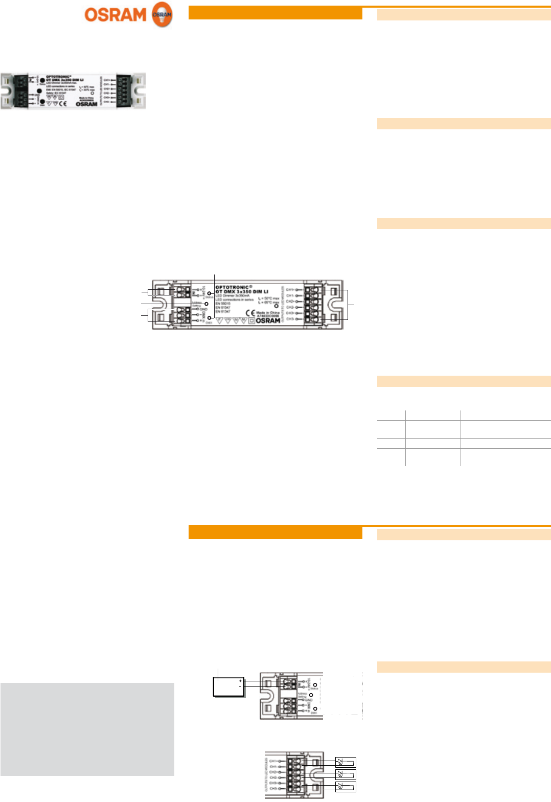
Page 1 of 2OSRAM GmbH Kunden Service Center Customer-Service-Center (CSC) Steinerne Furt 62 86167 Augsburg GermanyTel.: +49 (0) 1803 677 - 200 (kos

Page 2 - Appendix

Page 2 of 2Technical dataOperating voltage 10 … 24 VDCOutput current per channel 350 mAOutput load range per channel 0 … 8 W at 24 VDCMax. power loss

Comments to this Manuals

No comments